


Mixer Truck Gears
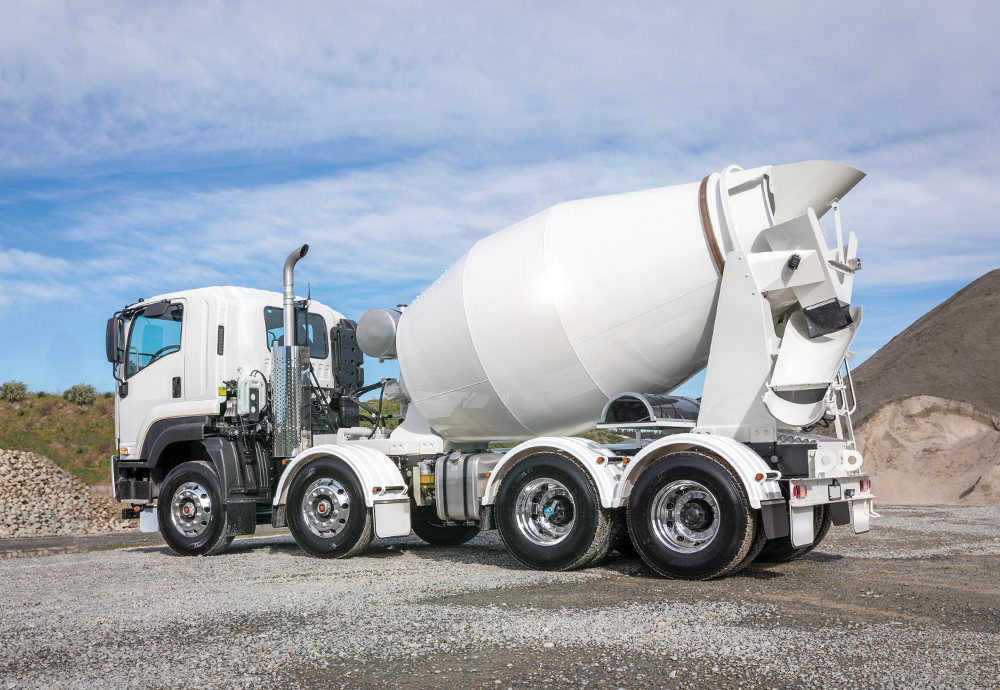
Mixer trucks, also known as concrete or cement mixers, typically have a few key components and gears that are essential for their operation. These gears help in mixing and transporting concrete efficiently. Here are some of the main gears used in mixer trucks:
- Mixing Drum: This is the primary component of the mixer truck. It rotates continuously during transit to keep the concrete mixture from hardening. The rotation is powered by hydraulic motors or sometimes by the truck's engine through a power take-off (PTO) system.
- Hydraulic System: Mixer trucks use hydraulic systems to power various functions, including rotation of the mixing drum, operation of the discharge chute, and raising or lowering of the mixing drum for loading and unloading. Hydraulic pumps, motors, cylinders, and valves are essential components of this system.
- Transmission: The transmission system is responsible for transferring power from the engine to the wheels. Mixer trucks usually have heavy-duty transmissions designed to handle the load and provide the necessary torque for moving the vehicle, especially when loaded with concrete.
- Engine: Mixer trucks are equipped with powerful engines to provide the required horsepower for moving heavy loads and operating the hydraulic systems. These engines are often diesel-powered for their torque and fuel efficiency.
- Differential: The differential gear assembly allows the wheels to rotate at different speeds while turning corners. This is crucial for maintaining stability and preventing tire wear in mixer trucks, especially when navigating tight spaces or uneven terrain.
- Drivetrain: The drivetrain components, including axles, driveshafts, and differentials, work together to transmit power from the engine to the wheels. In mixer trucks, these components are built to withstand heavy loads and provide reliable performance.
- Water Tank and Pump: Many mixer trucks have a water tank and pump system for adding water to the concrete mixture during mixing or to clean the mixer drum after use. The water pump is typically powered by a hydraulic or electric motor.
These gears and components work together to ensure that mixer trucks can effectively mix, transport, and discharge concrete at construction sites. Regular maintenance and inspection of these gears are essential to ensure safe and efficient operation.
Concrete Batching Plant Gears
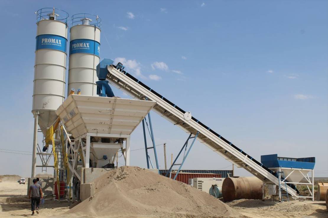
A concrete batching plant, also known as a concrete mixing plant or a concrete batching plant, is a facility that combines various ingredients to form concrete. These plants are used in large-scale construction projects where a continuous supply of high-quality concrete is required. Here are the key components and processes involved in a typical concrete batching plant:
- Aggregate Bins: These bins store different types of aggregates such as sand, gravel, and crushed stone. The aggregates are proportioned based on the required mix design and then discharged onto a conveyor belt for transport to the mixing unit.
- Conveyor Belt: The conveyor belt transports the aggregates from the aggregate bins to the mixing unit. It ensures a continuous supply of aggregates for the mixing process.
- Cement Silos: Cement silos store cement in bulk quantities. The cement is typically stored in silos with aeration and control systems to maintain the quality of the cement. Cement is dispensed from the silos through pneumatic or screw conveyors.
- Water Storage and Additive Tanks: Water is an essential ingredient in concrete production. Concrete batching plants have water storage tanks to ensure a continuous supply of water for the mixing process. Additionally, additive tanks may be included to store and dispense various additives such as admixtures, coloring agents, or fibers.
- Batching Equipment: Batching equipment, such as weighing hoppers, scales, and meters, accurately measure and dispense the ingredients into the mixing unit according to the specified mix design. Modern batching plants often use computerized control systems to automate this process and ensure precision.
- Mixing Unit: The mixing unit, also known as the mixer, is where the various ingredients are combined to form concrete. The mixer can be a stationary drum mixer, a twin-shaft mixer, or a planetary mixer, depending on the plant's design and capacity. The mixing process ensures thorough blending of aggregates, cement, water, and additives to produce a homogeneous concrete mixture.
- Control System: A control system oversees and regulates the entire batching process. It monitors ingredient proportions, controls the operation of conveyors and mixers, and ensures the consistency and quality of the concrete produced. Modern batching plants often feature advanced computerized control systems for efficient and precise operation.
- Batch Plant Control Room: This is where operators monitor and control the batching process. It typically houses the control system interface, monitoring equipment, and operator consoles.
Concrete batching plants come in various configurations and capacities to suit different project requirements. They play a crucial role in ensuring the timely supply of high-quality concrete for construction projects, ranging from residential buildings to large infrastructure developments. Efficient operation and maintenance of batching plants are essential to ensure consistent concrete production and project success.
Excavators Gears
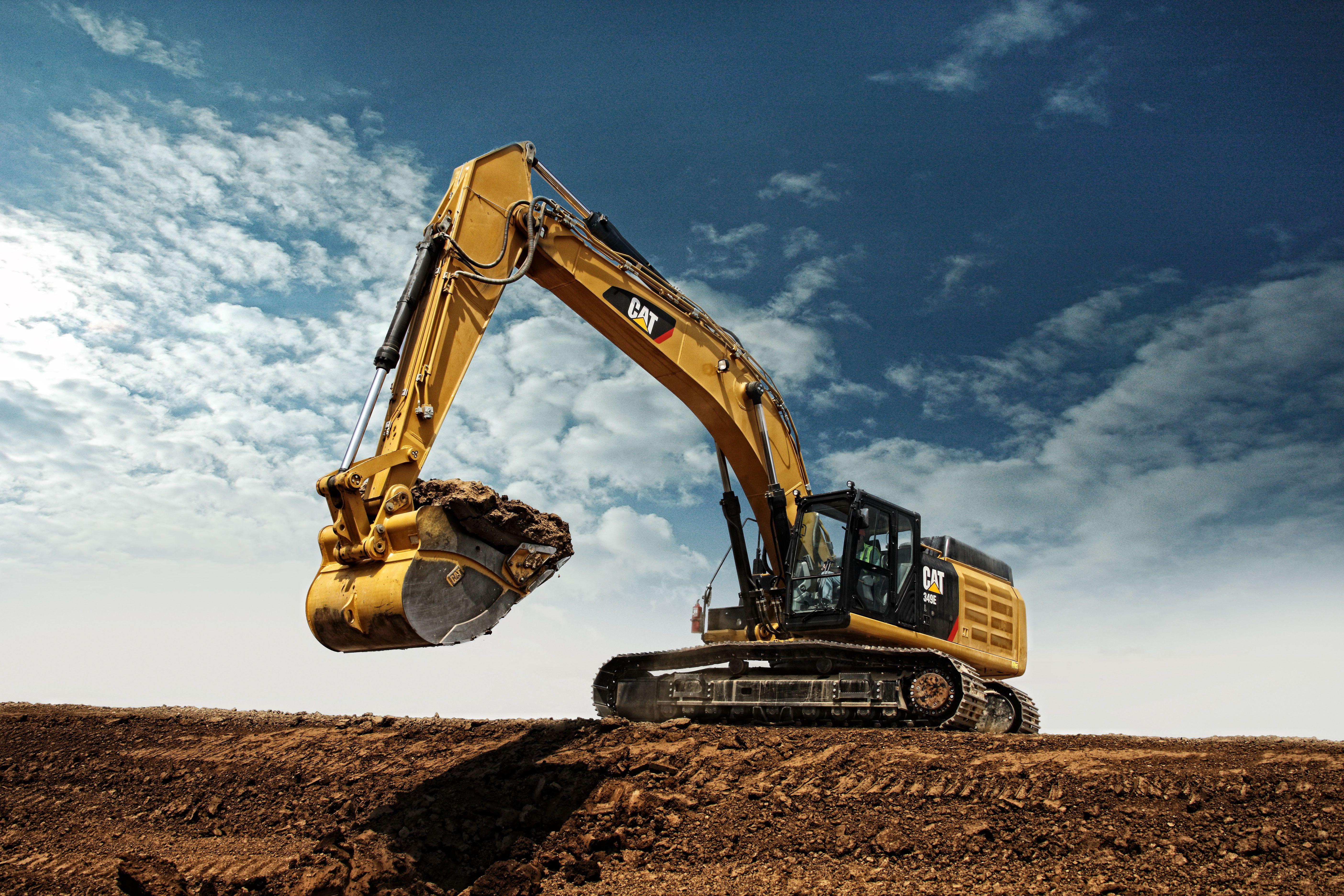
Excavators are complex machines designed for digging, demolition, and other earthmoving tasks. They utilize various gears and mechanical components to achieve their functionality. Here are some of the key gears and components commonly found in excavators:
- Hydraulic System: Excavators rely heavily on hydraulic systems to power their movement and attachments. Hydraulic pumps, motors, cylinders, and valves control the operation of the excavator's boom, arm, bucket, and other attachments.
- Swing Gear: The swing gear, also known as the slew ring or swing bearing, is a large ring gear that allows the upper structure of the excavator to rotate 360 degrees on the undercarriage. It is driven by hydraulic motors and allows the operator to position the excavator for digging or dumping materials in any direction.
- Track Drive: Excavators typically have tracks instead of wheels for mobility. The track drive system includes sprockets, tracks, idlers, and rollers. The sprockets engage with the tracks, and hydraulic motors drive the tracks, allowing the excavator to move over various terrains.
- Transmission: Excavators may have a transmission system that transfers power from the engine to the hydraulic pumps and motors. The transmission ensures smooth power delivery and efficient operation of the hydraulic system.
- Engine: Excavators are powered by diesel engines, which provide the necessary horsepower to operate the hydraulic system, track drives, and other components. The engine may be located in the rear or front of the excavator, depending on the model.
- Cab and Controls: The operator's cab houses the controls and instrumentation for operating the excavator. Gears such as joysticks, pedals, and switches allow the operator to control the movement of the boom, arm, bucket, and other functions.
- Bucket and Attachments: Excavators may be equipped with various types and sizes of buckets for digging, as well as attachments such as grapples, hydraulic hammers, and thumbs for specialized tasks. Quick couplers or hydraulic systems allow for easy attachment and detachment of these tools.
- Undercarriage Components: In addition to the track drive system, excavators have undercarriage components such as track tensioners, track frames, and track shoes. These components support the weight of the excavator and provide stability during operation.
These gears and components work together to enable the excavator to perform a wide range of tasks efficiently and effectively. Regular maintenance and inspection are essential to ensure the proper functioning and longevity of excavators in demanding work environments.
Tower Crane Gears
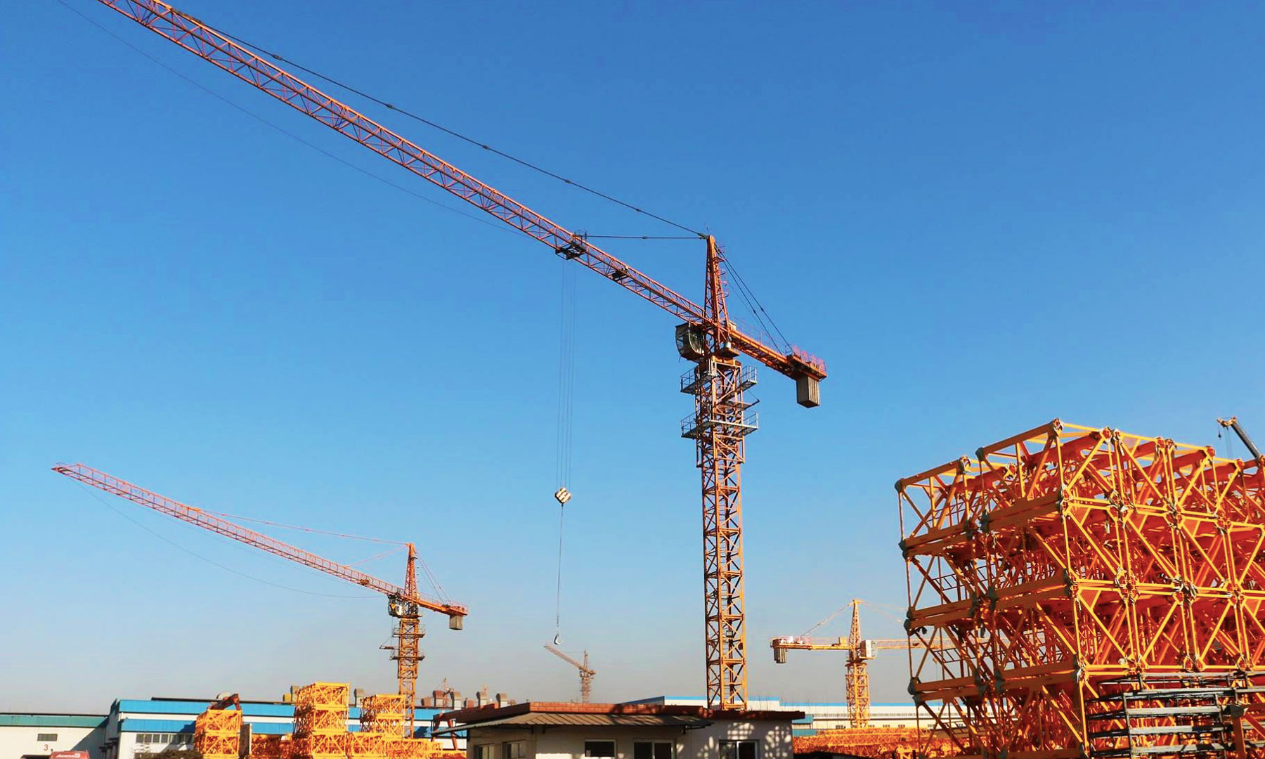
Tower cranes are complex machines used primarily in the construction of tall buildings and structures. While they don't use traditional gears in the same way as automotive vehicles or industrial machinery, they do rely on a variety of mechanisms and components to operate effectively. Here are some key elements related to the operation of tower cranes:
- Slewing Gear: Tower cranes are mounted on a vertical tower, and they can rotate (slew) horizontally to access different areas of a construction site. The slewing gear consists of a large ring gear and a pinion gear driven by a motor. This gear system allows the crane to rotate smoothly and precisely.
- Hoisting Mechanism: Tower cranes have a hoisting mechanism that lifts and lowers heavy loads using a wire rope and a hoist drum. While not strictly gears, these components work together to raise and lower the load. The hoisting mechanism may include a gearbox to control the speed and torque of the lifting operation.
- Trolley Mechanism: Tower cranes often have a trolley mechanism that moves the load horizontally along the jib (horizontal boom). This mechanism typically consists of a trolley motor and a gear system that allows the load to be positioned accurately along the jib.
- Counterweights: To maintain stability and balance while lifting heavy loads, tower cranes use counterweights. These are often mounted on a separate counter-jib and can be adjusted as needed. While not gears themselves, counterweights play a crucial role in the overall operation of the crane.
- Braking System: Tower cranes are equipped with braking systems to control the movement of the load and the rotation of the crane. These systems often include multiple brake mechanisms, such as disc brakes or drum brakes, which may be operated hydraulically or mechanically.
- Control Systems: Tower cranes are operated from a cab located near the top of the tower. The control systems include joysticks, buttons, and other interfaces that allow the operator to control the crane's movements and functions. While not gears, these control systems are essential for the safe and efficient operation of the crane.
While tower cranes don't use traditional gears in the same way as some other types of machinery, they do rely on various gear systems, mechanisms, and components to perform their lifting and positioning functions accurately and safely.
More Construction Equipments where Belon Gears


