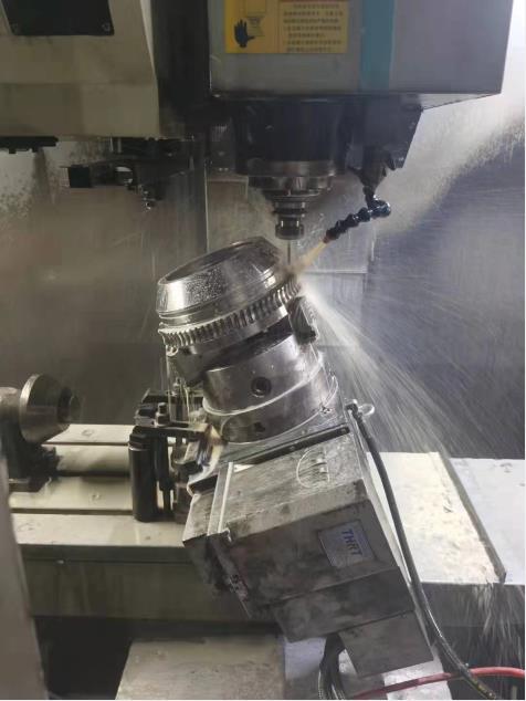
Worm gears are power-transmission components primarily used as high-ratio reductions to change the direction of shaft rotation and to decrease speed and increase torque between non-parallel rotating shafts. They are used on shafts with non-intersecting, perpendicular axes. Because the teeth of the meshing gears slide past each other, worm gears are inefficient compared to other gear drives, but they can produce massive reductions in speed in very compact spaces and therefore have many industrial applications. Essentially, worm gears may be classified as single- and double-enveloping, which describes the geometry of the meshed teeth. Worm gears are described here along with a discussion of their operation and common applications.
Cylindrical worm gears
The basic form for the worm is the involute rack by which spur gears are generated. Rack teeth have straight walls but when they are used to generate teeth on gear blanks they produce the familiar curved tooth form of the involute spur gear. This rack tooth form essentially winds around the body of the worm. The mating worm wheel is composed of helical gear teeth cut at an angle which matches the angle of the worm tooth. The true spur shape only occurs in the central section of the wheel, as the teeth curve to envelop the worm. The meshing action is similar to that of a rack driving a pinion, except the translational motion of the rack is replaced by the rotary motion of the worm. The curvature of the wheel teeth is sometimes described as “throated.”
Worms will have at least one and up to four (or more) threads, or starts. Each thread engages a tooth on the worm wheel, which has many more teeth and a much larger diameter than the worm. Worms can turn in either direction. Worm wheels usually have at least 24 teeth and the sum of the worm threads and wheel teeth should ordinarily be greater than 40. Worms can be made directly on the shaft or separately and slipped onto a shaft later.
Many worm-gear reducers are theoretically self-locking, that is, incapable of being back-driven by the worm wheel, an advantage in many instances such as hoisting. Where back-driving is a desired characteristic, the geometry of the worm and wheel may be adapted to permit it (often requiring multiple starts).
The velocity ratio of the worm and wheel is determined by the ratio of the number of wheel teeth to worm threads (not their diameters).
Because the worm sees comparatively more wear than the wheel, often dissimilar materials are used for each, such as a hardened steel worm driving a bronze wheel. Plastic worm wheels are also available.
Single- and Double-enveloping worm gears
Enveloping refers to the way in which the worm wheel teeth wrap partially around the worm or the worm teeth wrap partially around the wheel. This provides a greater contact area. A single-enveloping worm gear uses a cylindrical worm to mesh with the throated teeth of the wheel.
To give even greater tooth contact surface, sometimes the worm itself is throated--shaped like an hourglass--to match the curvature of the worm wheel. This setup requires careful axial positioning of the worm. Double-enveloping worm gears are complex to machine and see fewer applications than single-enveloping worm gears. Advances in machining have made double-enveloping designs more practical than they were in the past.
Crossed-axis helical gears are sometimes referred to as non-enveloping worm gears. An aircraft clamp is likely to be a non-enveloping design.
Applications
A common application for worm-gear reducers is belt-conveyor drives as the belt moves comparatively slowly with respect to the motor, making the case for a high-ratio reduction. The resistance to back-driving through the worm wheel can be used to prevent belt reversal when the conveyor stops. Other common applications are in valve actuators, jacks, and circular saws. They are sometimes used for indexing or as precision drives for telescopes and other instruments.
Heat is a concern with worm gears as the motion is essentially all sliding much like a nut on a screw. For a valve actuator, the duty cycle is likely to be intermittent and heat probably dissipates readily between infrequent operations. For a conveyor drive, with possibly continuous operation, heat plays a large role in the design calculations. Also, special lubricants are recommended for worm drives because of the high pressures between teeth as well as the possibility of galling between the dissimilar worm and wheel materials. Housings for worm drives are often fitted with cooling fins to dissipate heat from the oil. Almost any amount of cooling can be achieved so the thermal factors for worm gears are a consideration but not a limitation. Oils are generally recommended to stay below 200°F for there to be an effective operation of any worm drive.
Back-driving may or may not occur as it is dependent not only on the helix angles but also on other less-quantifiable factors such as friction and vibration. To assure that it will always occur or never occur, the worm-drive designer must select helix angles that are either steep enough or shallow enough to override these other variables. Prudent design often suggests incorporating redundant braking with self-locking drives where safety is at stake.
Worm gears are available both as housed units and as gearsets. Some units can be procured with integral servomotors or as multi-speed designs.
Special precision worms and zero-backlash versions are available for applications involving high-accuracy reductions. High-speed versions are available from some manufacturers.

Post time: Aug-17-2022


